Tuesday, May 4, 2021

Quiet LED Light Bulbs

I've been on a journey of tracking down sources of RFI from within my home, and one of the top offenders has been LED light bulbs.   Specifically, it's the switching mode power supplies (SMPS) within the LED bulbs or fixtures that cause the interference, generally not the LED itself.

We have a large number of 6" downlight / can fixtures in the house, and I've been through a number of different 65w (equivalent) LED bulbs looking for ones that are RF quiet.  After trying probably 10 different types, I've found ones that are quiet and work well.   They aren't cheap -- as they're not one of the Chinese brands that you find all over the internet.  

The latest GE LED bulbs work great.    Specifically the "Relax" series (BR-30 style), seems to be really quiet.  You can find them at the Big Box stores or online.    Although no bulb creates zero RFI, these haven't caused me any problems.   I just bought some GE Classic LED bulbs to try as well, and so far so good.

Tuesday, September 15, 2020

The Sun is Back!

NASA and NOAA announced today that Solar Cycle 25 has now officially started...


“How quickly solar activity rises is an indicator on how strong the next solar cycle will be,” says Doug Biesecker of NOAA’s Space Weather Prediction Center, co-chair of the Solar Cycle 25 Prediction Panel. “Although we’ve seen a steady increase in sunspot activity this year, it is slow.”

Tuesday, September 8, 2020

Replacing the Telrex Tri-Bander

About three years ago, I noticed a stuttering of the heading needle of my Tailtwister rotor control box as I turned the yagis on my tower, and I initially figured it was just dirty contacts on the pot in the rotor.  Nope.   I wish it was that simple.

The tower is a 100 feet of phillystran-guyed Rohn 45G with a pair of multiband yagis on top.   The lower antenna is a Telrex 10/15/20 meter tribander (circa early 90's) on a 26' boom, and the upper antenna is a Force12 12/17/20 meter yagi.

When they were installed in about 2000, the tops of the oak and poplar trees were about 7 to 10' lower than the lowest antenna.    They grew enough over the years to just catch the longest elements on the Telrex....  This damaged the elements, and the resulting bends created a weak spot that eventually doomed several pieces of tubing.     The antenna persisted for many months after being damaged, but eventually succumbed to the wind vibration and resulting metal fatigue where the elements had been bent.


Is it dicey having a guyed tower in a wooded location?   Yes....but it was a risk I was willing to take given the alternatives in my situation.   My main concern over the years has been a tree falling on a guy wire, which would likely bring the tower down -- so I've had to be vigilant in removing any trees that look like they might fall in the wrong direction.   What I didn't do is keep a close eye on what was happening up top!

This TB6EM was the best made Yagi for HF that I've  used...and it'll be missed.  The enormous diameter double walled boom utilized through-the-boom elements.   It was beautiful and she performed extremely well for decades, despite being a trapped design -- which we know today is lossy, compared to other multi-monobander approaches.    I'm in the middle of tree pruning now and making plans for taking down what remains of the Telrex, and then, I'll be selecting a new 21st century model to replace it.   This is a lot of work, but it'll be worth it.


Update 4/14/2021:

This winter I was able to clear back a number of trees that were interfering with my turning radius of the yagi, and made sure I have a 30' wide path from the ground up to the top of the tower.  I've fabricated a trolley from aluminum (will have a separate post on this) which will run from the ground to the top on two cables.   This will be used to remove the TB6EM and replace.    After looking at many, many designs -- I'm leaning towards the OptiBeam Log Yagi design.


Thursday, June 25, 2020

Weights for Tree Supported Wire Antennas

I'd been looking for a way to provide continuous tension on a wire antenna, like a doublet or a dipole, that is supported on one or both ends by a tree.   The idea is to run a line/rope from the end of the antenna, down through a pulley mounted high in the tree, and then to a weight hanging from the line; some people use springs to accomplish the same thing.   When the wind blows and the tree moves, the weight would move up and down, keeping more or less constant tension, thus keeping the antenna from snapping.  The ARRL Handbook and Antenna Book have had diagrams of doing stuff like this for decades...but finding a suitable weight can be an issue (besides getting the wire into the tree... that'll be another post...)

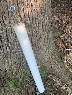
I've used a variety of things in the past including buckets full of dirt, cinder blocks, and even "no-weight" by just tying to the tree and hoping for the best, etc. but this time I wanted something that would minimize damage to the tree trunk should it swing into the tree and would be XYL friendly.     Below is what I've constructed from two feet of 2" and 3" PVC pipe, concrete, 12" of rebar, and a lag screw with a loop.

Alt Text
PVC-Concrete Antenna Weight

I mixed up the concrete in one of those plastic storage containers using a 60# bag of Sakrete High Strength mix (although any concrete should do) along with about 2 quarts of water.  After taping off one of the ends of the PVC with duct tape, I filled the pipe up with concrete and then inserted the rebar into the center, leaving about 2" sticking out.   (I had concrete leftover which I used for some driveway patching!)

Once it cured, my son welded the lag screws onto the end of the rebar.  Done.

I haven't weighed them yet, but it feels like about 10 lbs for the 2" pipe and maybe 20 for the 3".   Once I weigh them, I'll re-post my findings.   There's nothing magic about the length and size here, although bigger antennas are going to require more weight to prevent excessive sag.  And in my instance, the plan is to use a weight on just one end of the antenna.

73,
Rush, W4QA

Standard Wire Antenna Approach


2" PVC, Rebar, Lag Eye Bolt

Saturday, September 21, 2019

Fixing A Noise Problem on an Astron RS-35M

Ground Noise on Astron Power Supplies

Not too long after acquiring an Elecraft KX3 and the PX3 panadapter,  I experienced how useful having a real-time spectrum display was in tracking down noise problems.   It's interesting that several local noise problems revealed were ones that for the most part were not audible, particularly on an HF band with expected atmospheric noise levels masking a good bit -- but seeing is believing.

Astron RS-35M -- 1990's
One particular issue I ran into was low frequency (audio range 0-300 hertz) noise / spikes showing up on the PX3 when powering it from a 1990's vintage Astron RS-35M power supply -- one that has served me well for a long time for a number of purposes.
Running the Elecraft from either a battery, a Bioenno Power Pack, or a Pro Audio Engineering power supply eliminated the problem -- with everything else in the setup not changed.   It seemed either a ground loop of some sort or a failing component in the supply was likely the root cause.

Jim Brown, K9YC, published a white paper around an issue that sounded very similar to what I was seeing -- although he was initially validating that a transmit audio issue was being caused by a ground issue on the V- of some Astron supplies.  Repeater-Builder.com has also compiled much information on this subject as well and can be found here.

To net it out, particular Astron supplies manufactured at certain times have bonded the V-  (the negative/ black lead) output of the supply to the chassis, along with the "green wire" third pin on the standard AC plug.  In other words, the supply as manufactured this way is not a floating DC supply -- and anything on the AC safety ground will make its way to the V- feeding your rig and accessories, potentially causing noise current to flow through things you'd rather it not flow through.  Putting an ohmmeter from V- to the chassis will tell the story -- if there is something close to zero ohms, it is not floating.
RS-35M with Negative Bonded to Chassis


In my case, checking the resistance revealed .006 ohms between the chassis and the negative terminal, so I cracked open the case to see how this was achieved.   Simply, a black 16 gauge lead ran from the circuit board "ground" to a screw with star washers on the bottom of the chassis -- this was in parallel to another wire that went from the same solder pad to the V- terminal on the rear. (It is interesting that the V- terminal is actually insulated from the chassis, go figure)   I disconnected the chassis wire, heat shrink wrapped the now disconnected terminal (if for some reason I wanted to reconnect later), and put the cover back together.   Plugged it in, tested the voltage, powered up the KX3 / PX3 and -- No Noise.

Maybe this workhorse will be around the shack another 10 years!

Saturday, September 14, 2019

Liquidambar Styraciflua Needs An Antenna

There are a LOT of trees on my property.  And that is both a blessing and a curse for antenna work.  I tend to be an optimist, so focusing on the blessing part works better for me...

Given where we are in the sunspot cycle, I've been considering ways to bolster W4QA's DX performance on the lower bands.  Specifically, 80 meters has always been a weak point in my antennas situation for the usual reasons:  you need room, you need elevation.     If maximum efficiency is desired, there's just little substitute for size -- and that goes for both horizontal and vertical antennas (including the radial / GP system).

So in that context, this tree in my backyard -- about 125' from the house and maybe 90' high, is begging to be a useful support for 'something'; for now, that 'something' is going to be a full-sized, 1/4 wave, 80 meter wire vertical with elevated radials.  This tree (Liquidambar Styraciflua), what we call a "Sweet Gum" tree in the Carolinas,  aren't that useful for much other than firewood, and, well antenna supports. (The seed pods are a devil to deal with in your yard...but that's another topic.)

In general, the vertical element will be made out of 13 gauge stranded / insulated copper wire and the radials from 18 gauge stranded / insulated copper wire -- all from The Wire Man (no affiliation).   The feedpoint will incorporate a choke/unun and depending on the Z measurements, I may design some type of simple matching (possibly a shunt inductor at the base (?)) to raise the input impedance closer to 50 ohms. 

Look for more posts as this develops and I welcome comments....

73, Rush